Common sleeve settings
In [project] > Specifications > Construction > Common Sleeve Settings, project administrators can add, modify, and delete common sleeve settings for multi-pipe penetrations. Designers select which settings to use when they insert a multi-pipe penetration as described in Multi-Pipe Penetration with Sleeve.
Common sleeve settings define what should be the size of the sleeve when the penetrating pipe has a certain Nominal Size. The settings also define whether the sleeve is constructed by using only plate materials or by using plate materials together with sleeve parts.
Defining common sleeve settings
Perform the following to define common sleeve settings.
Do the following:
-
In the Project Environment dialog, go to [project] > Specifications > Construction > Common Sleeve Settings.
-
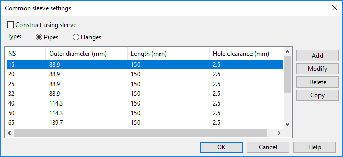
Select New > Construction Settings to create new common sleeve settings, or double-click an existing settings object to edit it. The 'Common sleeve settings' dialog opens.
-
Construct using sleeve – If selected, the common sleeve is constructed by using plate material for the straight segments and (split) sleeve parts for curved segments. If this is selected, the hull plate material mappings must define a catalog part for both the plate material and the sleeve part. Clear this setting to use only plate materials for the whole construction.
 Show/hide details
The catalog part used for the common sleeve must have the following named dimensions:
-
WTsleeve – sleeve wall thickness
-
ODsleeve – sleeve outer diameter
-
Lsleeve – sleeve length
When constructing the common sleeve, the sleeve catalog part size is found by matching ODsleeve with the Outer diameter setting from the used settings row.
In addition, to be able to compute mass for the common sleeve, the plate material must have either density or mass/area defined, and if the common sleeve is constructed using a sleeve part, the catalog part must have mass defined.
-
-
Type – Select whether to define settings for pipes or flanges.
Important: You must always enter values for pipes. Enter values also for flanges if sleeve size should be computed from flange diameter values rather than from pipe diameter values.
-
Click Add to add a new Nominal Size, or select an existing Nominal Size row and click Modify to edit its current values. The value editor opens.
-
In the value editor, specify the following values for the pipe or flange:
- Nominal Size (NS) – Specifies the Nominal Size of a pipe that passes through the common sleeve.
- Outer Diameter (mm) – Specifies the outer diameter of the common sleeve for the specified Nominal Size. If you specify this value for a flange, when a designer is inserting a multi-pipe penetration and the penetrating pipes have flanges, the size of the common sleeve is calculated from flange diameter by default, but designer can set it to be calculated from pipe diameter.
- Length (mm) – Specifies the length of the common sleeve for the specified Nominal Size.
- Hole clearance (mm) – Specifies a clearance between the common sleeve outer border and the hole in the target plate.
-
Click OK.

Results
Designers can select to use these common sleeve settings when inserting a multi-pipe penetration. If the penetrating pipes have flanges and the common sleeve settings define flange values, sleeve size is calculated from flange outer diameter by default.